Video of the Day. Put the switch into the OFF position.

When you remove the light bulb the tester will not light up when the switch is ON or in OFF position.
Using a multimeter to test a light switch. Steps to testing a light switch using a multimeter. Switch off the power. Test for any power on the light switch.
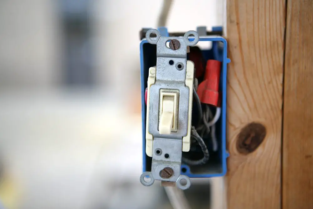
Identify the type of switch. Take out the light switch. Testing the switch for the continuity.
Replacing or reconnecting the switch. Very easy way to test light switch with multimeter. Make your to turn the power off at your breaker.
Connect the red lead to one of the terminals on the switch. Connect the black lead to the other terminal on the switch. Put the switch into the ON position.
The meter should display 1 ohm or less meaning the switch is ON. Find a live working outlet place the probe end near the smaller opening for the plug thats the hot side. The probe should light up and make a noise.
You dont need to touch anything just get with in an inch or so. Now that you know it works turn your switch on use the probe to check for power at it then go to each light and test for power. The best way to test whether or not the light switch is working or not is to remove the filament in the light bulb and then perform the test.
When you remove the light bulb the tester will not light up when the switch is ON or in OFF position. This will light up only when the switch is ON. The above test is conducted to test the light switch using a multimeter.
You may interested in. If you dont happen to have a working bulb handy you can use a light socket tester or test the fixture with a multimeter. There are two procedures to check a light socket with a multimeter one of which requires the power to be on and another you can do with the power off.
Video of the Day. How to Test a Switch With an Ohm Meter. Verify ohm meter operation.
Turn on the multimeter. Insert the leads into the meter Touch the probe tips together to verify that ohm meter is functioning. Connect the red lead to one of the terminals on the switch.
Put the switch into the OFF position. Operate the switch on and off for a few more times. The tester should light up when the switch lever is in the on position but should not light up when the switch lever is off.
If it doesnt exhibit this behavior it indicates the inner connections are bad and that the switch needs to be replaced. If youre using a multimeter set the instruments dial to the Continuity or ResistanceOhms setting. You can use the ohm meter set on its lowest scale or the continuitydiode test setting.
Connect the leads to the two terminals and then apply pressure to the brake light switch. On the ohm scale it will go from open to an ohm maybe half an ohm depending upon the connection and internal resistance. Testing RegulatorRectifier Diodes with a Multimeter Set your multimeter to the diode setting.
Put the negative lead from the test probe to one terminal from a diode and put the positive lead from the test probe to another terminal from the diode. A continuity tester can be used to test the light switch while the circuit is OFF or the switch has been removed. This type of tester has two lead wires that uses the battery voltage of the tester to test a circuit which in this example is the circuit components of a switch.
Toggle the switch into the on and off position with the test leads. A digital multimeters Continuity Test mode can be used to test switches fuses electrical connections conductors and other components. A good fuse for example should have continuity.
A DMM emits an audible response a beep when it detects a complete path. Measure the batterys voltage using your multimeter and make sure the key is positioned at the run position on your ignition switch. If the multimeter displays a voltage of less than 90 of your batterys voltage then its without a doubt you have a faulty ignition switch.
Remove the light shade from the light fixture. Remove the light bulb to access the screws that hold the fixture canopy to the electrical box. Remove the screws to lower the canopy from the ceiling and access the electrical wiring.
Turn the dial on your multimeter tester to 250 AC to test the circuit for electrical power. With your multimeter to Volts DC mode probe the wire that corresponds to the number 6 with the red multimeter test lead. Since the Gray connector has to remain connected to the Instrument Panel Harness you need to probe the wire somewhere between the Gray connector and the turn signal switch using an appropriate tool like a Wire Piercing Probe.