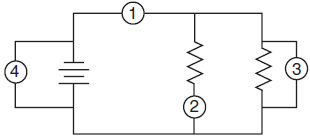
For instance a voltmeter can be used to see if there is more electricity left in a battery. The voltmeter is connected in parallel to the lamp You can measure the voltage across a cell or battery.

Electrical meters moving coil voltmeter and ammeter connected in where should an be placed a why you can t measure voltage to cur 18 2 parallel circuits series.
Where does a voltmeter go in a circuit. Where Do Voltmeters And Ammeters Go In A Circuit. Electrical meters moving coil voltmeter and ammeter connected in where should an be placed a why you can t measure voltage to cur 18 2 parallel circuits series. The voltmeter is always connected in parallel in the circuit because the pressure coil used in the voltmeter is made of thin wire and high resistance.
If we add the voltmeter in series then the voltage in the circuit in which it is connected drops. The voltmeter measures the difference between the two voltages of the circuit which we call the. A voltmeter is an instrument used for measuring electrical potential difference between two points in an electric circuit.
An ammeter is a measuring device used to measure the electric current in a circuit. A voltmeter is connected in parallel with a device to measure its voltage while an ammeter is connected in series with a device to measure its. Since voltmeters are always connected in parallel with the component or components under test any current through the voltmeter will contribute to the overall current in the tested circuit potentially affecting the voltage being measured.
The voltmeter indicates polarity by direction of needle direction analog or sign of numerical indication digital. When the red test lead is positive and the black test lead negative - the meter will register voltage in the normal direction. The instrument which measures the voltage or potential in volts is known as the voltmeter.
It is represented by the alphabet V inside the circle along with the two terminals. The voltmeter always connects in parallel with the circuit. The voltmeter is connected in parallel with the component.
The supply voltage is shared between components in a series circuit so the sum of the voltages across all of the components in a series. Circuit with cell lamp and voltmeter. The voltmeter is connected in parallel to the lamp You can measure the voltage across a cell or battery.
A voltmeter connected to a circuit board. A voltmeter is an instrument used to measure voltage. For instance a voltmeter can be used to see if there is more electricity left in a battery.
The creation of voltmeters became possible when Hans Oersted invented the most simple voltmeter in 1819. A voltmeter is an instrument used for measuring electrical potential difference between two points in an electric circuitA voltmeter is connected in parallel with a device to measure its voltage while an ammeter is connected in series with a device to measure its current. A voltmeter also known as a voltage meter is an instrument used for measuring the potential difference or voltage between two points in an electrical or electronic circuitSome voltmeters are intended for use in direct current DC circuits.
Others are designed for alternating current AC circuits. Car Battery Voltmeter Circuit Description. The main onjective of the car batter voltmeter circuit using LED is to work as a warning inducator using a voltmeter circuit to test the life of car batteries.
A voltmeter though can be bought from a store is designed as a circuit to make the whole arrangement a lot more interesting. For the purposes of this brief article well just focus on the supply side of this bulb circuit which goes from terminal 1 to terminal 4. Usually a tech grounds the voltmeter by connecting its negative lead to the negative battery post.
If you simply measure the battery voltage with a voltmeter you get a higher reading due to the fact that there is no or very little voltage dropped across the internal battery resistance. The voltage measured across a load resistor or bulb OR the terminals of the battery will be smaller by an amount equal to I. Voltmeters measure voltage and ammeters measure current.
A voltmeter is placed in parallel with the voltage source to receive full voltage and must have a large resistance to limit its effect on the circuit. An ammeter is placed in series to get the full current flowing through a branch and must have a small resistance to limit its effect on. The power-supply current should go as much as possible towards operating whatever circuit or system you want to use not into getting a meter to tell you the voltage.
Also you might not want to keep the voltmeter constantly connected in parallel in the circuit. You might need the voltmeter for testing many different circuits. When the switch is open the voltmeter reads the voltage across R1.
R3 is irrelevant in this situation and might as well be a short circuit. When the switch is closed the voltmeter reads the voltage across R2. Any measuring device has limited accuracy and to one extent or another affects the behavior of the circuit it is measuring.
Voltmeters which are by design relatively high input impedance devices will nonetheless place some finite load on the circuit they are measuring drawing some finite current from that circuit in the process and thus having some finite affect on the voltage at the point in the circuit. A voltmeter must be connected in parallel to measure the voltage of a device because objects in parallel experience the same potential difference. A voltmeter is used to measure the electrical potential difference between two locations in an electrical circuit.
Two devices used to measure electric current and voltage are the voltmeter and ammeter.